A technician once spent two hours troubleshooting a bit-error problem on a 1.6 km single-mode campus link. The total optical loss was less than 2 dB, and every connection appeared normal on the test trace, yet the link continued to fail. The cause was connector end-face contamination hidden inside the dead zone of a long-pulse OTDR (Optical Time Domain Reflectometer) trace. The fault was invisible because the OTDR was configured to maximize measurement distance (reach) when the task actually required high resolution.
This scenario is common. In data centers, enterprise Local Area Networks (LANs), FTTx drop segments, and AI computing networks, fiber links are frequently shorter than 2 km, and sometimes shorter than 100 m. These links contain a high density of connectors, patch panels, and MPO (Multi-Fiber Push-On) cassette interfaces. In these environments, the most critical OTDR specification is not the maximum distance the instrument can measure, but its ability to distinguish closely spaced physical events.
The Unavoidable Technical Compromise
An OTDR transmits a pulse of light and detects Rayleigh backscatter. The pulse width (measured in nanoseconds or microseconds) determines two competing outcomes:
- Longer pulse width: Injects more energy and keeps the returning signal above the noise floor for a greater distance, resulting in a higher dynamic range.
- Shorter pulse width: Restricts the light burst to a smaller physical length of fiber. This reduces both the event dead zone (the minimum distance required to separate two reflective events) and the attenuation dead zone (the minimum distance required after a reflection before signal loss can be accurately measured).
Dynamic range and dead zone represent a physical limitation. An OTDR can be optimized for distance or for resolution, but it cannot maximize both simultaneously.
The Actual Requirements for Short-Reach Testing
In a data center or enterprise network, total optical loss is typically very low. A 1.6 km single-mode link with two to four patch-panel connections usually has less than 2 dB of total loss. The dynamic range required to test this link is typically between 10 dB and 15 dB. Almost any OTDR can provide this dynamic range, even when using a narrow pulse width setting.
However, a short dead zone is strictly required. A short-reach link contains many closely spaced reflective events, such as MPO connectors at cassettes, LC connectors at patch panels, and short patch cords between network switches. For example, Fluke Networks designs data-center OTDRs with dead zones short enough to test 0.5 m patch cords. EXFO specifies event dead zones of 0.5 m and attenuation dead zones of 2.0 to 2.5 m at their narrowest pulse settings. These specifications are necessary because short-reach environments cannot tolerate testing blind spots of one meter or more.
Therefore, a short-reach OTDR does not have a lower dynamic range because it is a low-quality instrument. It has a lower dynamic range because its design relies on narrow pulses, short dead zones, and fast receiver recovery times. These design choices naturally reduce the maximum measurable distance. The reduced dynamic range is the necessary compromise to achieve short dead zones. The primary goal is resolution.
A Controlled Comparison of Pulse Widths
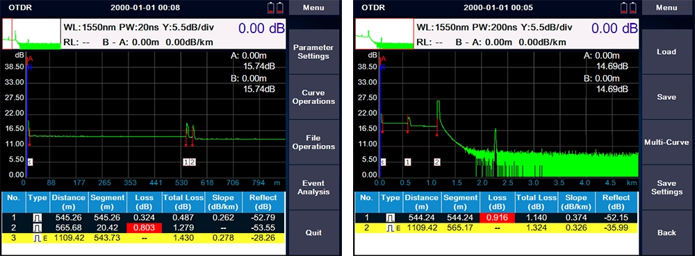
A simple laboratory setup demonstrates this principle clearly (see Figure). Connect two 545 m fiber spools using a 20 m patch cord, utilizing UPC (Ultra Physical Contact) connectors at both junctions. From the testing end, the two connectors are located at approximately 545 m and 565 m (only 20 m apart). The total link loss remains constant; only the OTDR pulse width changes during the test.
- At a 200 ns pulse width: The two connectors fall within a single event dead zone. The OTDR displays one combined event near the 545 m mark. The second connector is still physically present, but the OTDR cannot detect it as a separate event because it is hidden inside the dead zone of the first connector.
- At a 20 ns pulse width (or the narrowest available setting, typically 5 to 10 ns): The OTDR successfully detects two distinct reflective peaks and reports two separate events. At 20 ns, the OTDR might separate the physical positions, but the attenuation dead zone may still prevent accurate loss measurement of the second event. For this reason, operators must use the narrowest possible pulse width when connectors are close together.
Download sor files
The Misconception of High Dynamic Range
Many OTDRs advertise high dynamic ranges of 37 dB, 39 dB, or more. These instruments are excellent for long-haul networks, metro networks, and PON (Passive Optical Network) feeder testing. However, manufacturers measure maximum dynamic range using the longest possible pulse width. When configured this way, an OTDR with a 39 dB rating might have a dead zone of 10 meters or more. In a data center, a 10-meter testing blind spot is a severe operational risk.
Conversely, an OTDR with a lower dynamic range (15 to 20 dB), sub-meter event dead zones, and high sampling resolution will perform much better on a 500 m data-center link than a 40 dB long-haul OTDR. The link length and the density of the connectors determine which instrument is appropriate.
Important Note: While a shorter pulse improves resolution, it does not automatically guarantee a shorter dead zone. Equipment manufacturers like EXFO emphasize that the receiver’s bandwidth and recovery time are equally important. Therefore, buyers should compare the published dead-zone specifications at the exact same reflectance level. The goal is to verify that the OTDR’s published dead zone (at its narrowest usable pulse) is shorter than the physical distance between connectors in the network, while ensuring the dynamic range is sufficient for the total link loss.
A Practical Framework for OTDR Selection
To select the correct OTDR, match the instrument specifications to the physical characteristics of the network:
- Links under 2 km (especially with multiple patch panels or MPO interfaces): Prioritize the event dead zone and attenuation dead zone. Choose instruments with sub-meter event dead zones and attenuation dead zones of less than 5 meters at the narrowest pulse setting. Confirm that the dynamic range at this narrow pulse setting is at least 5 to 8 dB greater than the link’s total optical loss.
- Links between 2 km and 20 km (campus backbone or metro access): The testing requirements are more balanced. A medium pulse width (30 to 100 ns) provides event dead zones of approximately 5 to 20 m and offers sufficient dynamic range for these distances. Evaluate both dynamic range and dead zone equally.
- Links over 20 km (or PON feeder segments with high split ratios): Dynamic range is the primary requirement. However, if the near-end of the link contains many connectors, operators must use a short pulse to test the first few hundred meters, and then use a longer pulse for the remaining distance. Modern OTDRs automate this process using multi-pulse testing modes.
Universal Operating Principle: Always start testing with the shortest pulse width that produces a clear signal trace at the far end of the link. Only increase the pulse width if the signal becomes too noisy or if the end of the link cannot be detected. Do not use automated settings that default to long pulses merely to produce a visually “smooth” trace, as this eliminates the resolution required for short-reach testing.
Conclusion
When selecting an OTDR for short-reach testing, do not simply search for the highest dynamic range specification. Choose an instrument designed for the physical reality of the network: short distances, high connector density, and zero tolerance for measurement blind spots. A lower dynamic range is an acceptable consequence of optimizing the instrument for these conditions. The most critical specification for short-reach testing—and the one that determines if a faulty connector remains hidden—is the dead zone.
Disclosure: The author’s organization supplies fiber-optic test equipment for short-reach and data-center applications. The technical framework above is based on published application notes from EXFO and Lambda Photometrics, and manufacturer specifications from Fluke Networks and EXFO. The opening troubleshooting scenario is an illustrative example, not a specific case study. The comparison trace described in Figure 1 is based on a controlled laboratory demonstration, not field data.
Visit FirstFiber Techonologies OTDR