Safety Warning
Power Adapter
Input: AC 100-240V, 50/60Hz, 0.8A
Output: DC 5V, 1A (USB Type-C)
Note: Please use a power adapter that strictly complies with these specifications. Using an incompatible adapter may result in damage to the device.
Battery
This instrument contains a built-in lithium battery. To optimize battery performance, please run the instrument on battery power during your initial use until it is fully depleted before recharging.
The initial charge should take at least 5 hours. The safe charging temperature range is -10°C to 50°C; for safety reasons, stop charging if the temperature exceeds this limit.
If the instrument remains unused for more than 3 months, recharge the battery periodically to maintain its capacity. The recommended temperature range for long-term storage is -20°C to 45°C.
Warning: Do not attempt to remove the battery yourself. Keep the device away from fire and extreme heat. Do not open, puncture, or otherwise damage the battery.
Laser Safety Instruction
Laser Safety Classifications:
- OTDR: Class II
- Visual Fault Locator (VFL): Class IIIB
⚠️ WARNING: EYE HAZARD
Do Not Look Directly at the Laser: The lasers emitted by this device are hazardous. Never look directly into the laser output ports or the end of an optical fiber while the instrument is active or testing.
VFL Precautions: Strict caution is required when the Visual Fault Locator is turned on. Direct eye exposure to the VFL output port or the connected fiber end can cause severe eye injury.
Port Protection: Always replace the dust caps on the optical output ports whenever the instrument is not in use.
Know Before Testing
Live Fiber Test (In-service Test)
| Model | Operating Wavelength | Live Fiber Testing Support |
|---|---|---|
| TN1700-D22 | 1310 nm / 1550 nm | Not supported |
| TN1700-P1 | 1550 nm | Supported (1310/1490/1577/1610/1625 nm) |
| TN1700-P2 | 1610 nm | Supported (1310/1490/1550/1577 nm) |
| TN1700-A22 | 1625 nm | Supported (1310/1490/1550/1577 nm) |
Note: For supported models, live fiber testing is strictly prohibited if the optical power exceeds 0 dBm.
Laser Type
1310/1550 nm: FP-LD
1610 nm: DFB-LD
1625 nm: DFB-LD
1650 nm: DFB-LD (Optional)
VFL (Visual Fault Locator): 650 nm (red) and 515 nm (green) lasers are available as optional add-ons.
Test Result Storage
Storage & Memory:
- Built-in memory
- SD card expansion slot (supports up to 32 GB)
⚠️ Important: Avoid overloading the SD card with excessive data, as this may slow down the device and impact overall performance.
Main Functions and Button Descriptions
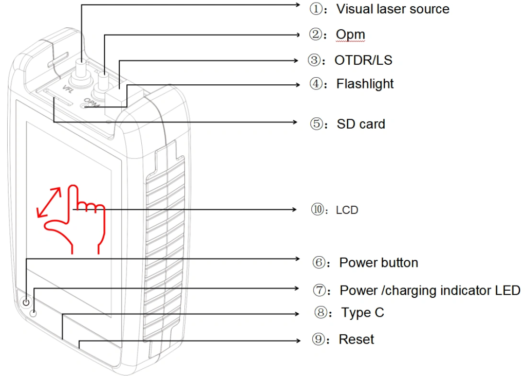
| Function | Description | |
| 1 | VFL | Visual Fault Locator Port |
| 2 | OPM | Optical Power Meter Port |
| 3 | OTDR/ LS | OTDR/Laser Source port |
| 4 | Flashlight | Short press the power button to operate |
| 5 | SD card | Supports up to 32GB SD card expansion |
| 6 | Power button | POWER ON/OFF -Long press: power on/off -Short press: Turn on/off flashlight |
| 7 | LED | -Red indicator charging, fully charged and turned off. -Flashing indicator: No battery installed |
| 8 | USB Type C | Used for charging and transmitting data |
| 9 | Reset key | Used to reset the instrument panel when a system crash occurs |
| 10 | LCD | resolution: 320X480 TFT Capacitive LCD screen, supporting multi touch control. |
Operating the TN1700
Power On
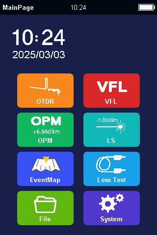
Press the [Power] button to turn on the TN1700. Once powered on, the screen will display the main interface.
Power Off
Long-press the [Power] button to shut down the device.
Flashlight Control
While the device is on, short-press the [Power] button to toggle the flashlight on or off.
Shortcut Menu
Swipe down from the top of the screen at any time to access the quick menu. Available options include: [Screenshot], [Flashlight], [Shutdown], and [Return].
System Settings
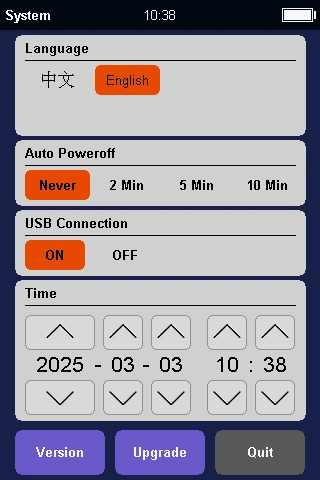
Language: Supports English, French, Spanish, Portuguese, Italian, German, Korean, and Russian.
Auto Off: To conserve battery, the device can automatically shut down after a period of inactivity. You can customize the idle time based on your needs.
USB Data Export: Connect the instrument to a computer and enable “USB Data Export”. The device will be recognized as a USB flash drive, allowing you to easily view, manage, and transfer files.
Date and Time: If the battery is removed, the system clock will reset. You will need to reconfigure the date and time after reinstalling the battery.
Firmware Upgrade
- Transfer the firmware upgrade package to the instrument via a USB cable.
- Disconnect the USB cable, then tap [Upgrade].
- The TN1700 will automatically enter upgrade mode and complete the firmware installation.
OTDR Parameter Settings
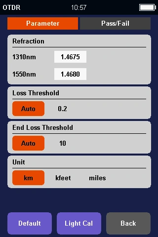
Wavelength: 1310 / 1550 nm (Configured by instrument model)
Test Mode (Auto/Manual):
- Auto: The instrument automatically selects the optimal measurement range and pulse width based on the fiber’s characteristics.
- Manual: The instrument uses the exact range and pulse width specified by the user.
Range: Select from 100 m up to 80 km.
Pulse Width: Select from 5 ns up to 10 μs.
Time: 5 s / 10 s / 30 s / 60 s / Real-time.
Refractive Index: The index of refraction for the fiber under test. Accuracy here directly impacts the precision of distance measurements.
End Threshold: When the optical loss at a specific location exceeds this threshold, that point is identified as the end of the fiber cable.
Loss Threshold: Used to filter event reporting; any event with a loss less than this value will be ignored.
Fiber Preparation
The TN1700 OTDR is designed to work with standard single-mode optical fibers (9 μm core diameter).
Please note that due to inherent OTDR testing principles, the length of the fiber under test must be between 3 meters and 80 km. Fibers shorter than 3 meters cannot be accurately measured.
Fiber Connector
There are two types of fiber connectors: APC (featuring an 8° angled end-face) and UPC/PC (featuring a flat end-face).
⚠️ Warning: APC and UPC connectors are strictly not interchangeable. Do not attempt to modify or switch the connector type yourself. By default, the OTDR port comes factory-equipped with an SC connector.
Connector Cleaning Guide
Please use a dedicated optical connector cleaner to clean both the OTDR port and your fiber connectors.
- To clean the OTDR port: Remove the entire dust cap from the tip of the cleaner.
- To clean a fiber connector: Remove only the top half of the dust cap from the cleaner tip.
Start a Test
Starting the OTDR Test
Once the cleaning process is complete, carefully insert the fiber connector into the OTDR port.
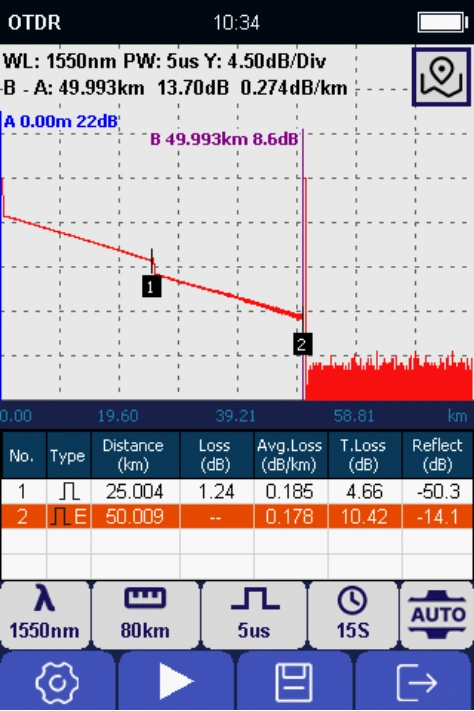
| Curve Part | |
| WL | Wavelength |
| PW | Pulse width |
| Y | Vertical axis scale in dB |
| A | The position of cursor A in distance, and loss at current position |
| B | The position of cursor B in distance, and loss at current position |
| A-B | Distance between A and B Loss value between A and B |
| Event List Part | |
| Number | Event number from near end to far end |
| Type | Attenuation event or reflect event |
| Distance | The distance from first event to current event. Km in unit |
| Loss | The loss value at current event dB in unit |
| Avg.Loss | The average loss/km from first event to current event |
| T.Loss | The total loss from first event to current event dB in unit |
| Reflect | The reflect signal value dB in unit |
To save OTDR Testing Results
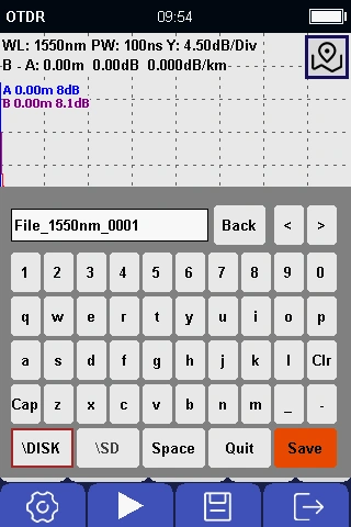
After testing is done, press [Save] button to save OTDR testing results.
| Description | |
| Cap | Toggle uppercase/lowercase letters |
| Clr | Clear current input |
| Back | Delete one letter from right side to left side |
| < | Move cursor from right to left and then insert a letter |
| > | Move cursor from left to right and then insert a letter |
| Quit | Back to OTDR testing and do not save current curve |
| \OTDR | Save to TN1700 |
| \SD | Save to SD card |
File Management
- Rename a File: Navigate to the File Management interface, select the desired file, and press the [Rename] button to enter a new name.
- Delete a File: Navigate to the File Management interface, select the file you wish to remove, and press the [Delete] button.
Event Map
| Name | Description |
| Number | Event number from near end to far end |
| Type | Attenuation event or reflection event |
| Distance | The distance from first event to current event.Km in unit |
| Loss | The loss value at current event, dB in unit |
| Avg.Loss | The average loss/km from first event to current event |
| T.Loss | The total loss from first event to current event dB in unit |
| Reflect | The reflected signal value (in dB) |
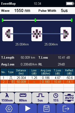
* To view the OTDR trace, press the [OTDR] button to open the trace display interface.
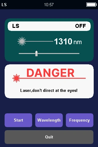
Light Source (OLS) Module
The Laser Source function utilizes the same internal laser module as the OTDR, ensuring their operating wavelengths are identical.
Turn On/Off
Press the [Start] button to activate the laser source. When active, the laser icon in the center of the screen will turn red. When deactivated, the icon will revert to gray.
Change Wavelength
Press the [Wave Switch] button to toggle between wavelengths. (Note: Available wavelengths depend on your specific OTDR model.)
Change Frequency
Press the [Freq Switch] button to adjust the modulation frequency. Available options are CW (Continuous Wave), 270 Hz, 330 Hz, 1 kHz, and 2 kHz.
Exit
Press the [Quit] button to return to the main interface.
⚠️ WARNING: EYE HAZARD
Never look directly into the laser output port. The emitted laser is invisible but extremely hazardous to the eyes.
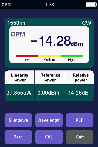
Optical Power Meter (OPM) Module
Turn On
Press the [Start] button to activate the Optical Power Meter.
Change Wavelength
Press the [Wave Switch] button to select the desired wavelength. Available options are 850 nm, 1300 nm, 1310 nm, 1490 nm, 1550 nm, 1625 nm, and 1650 nm.
Set Reference (REF)
Press the [REF] button to set the current optical power reading as your reference baseline (for relative power measurements).
Set Zero
Press the [Zero] button to perform a zero calibration, ensuring measurement accuracy.
Exit
Press the [Quit] button to return to the main interface.
User Calibration
Users can manually calibrate the Optical Power Meter (OPM) to ensure ongoing measurement accuracy. Follow these steps:
- Select Wavelength: Access the ‘Wavelength’ menu to select the specific wavelength you wish to calibrate.
- Adjust Power Value: Move the cursor to highlight the power input field. Use the [Up] and [Down] directional keys to match the standard reference power value.
- Confirm and Exit: Press the [OK] button to confirm your adjustment, then exit the interface to complete the calibration process.
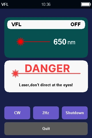
Visual Light Source (VFL) Module
The VFL supports two operating modes: CW (Continuous Wave) and 2 Hz (Flashing).
Mode Selection
Press the [CW] button to activate continuous illumination. Press the [2Hz] button to activate the flashing mode.
Turn Off
Press the [Shutdown] button to turn off the VFL. When deactivated, the laser icon in the center of the screen will revert to gray. When active, it will turn red.
Exit
Press the [Quit] button, then press [OK] to return to the main interface.
⚠️ WARNING: EYE HAZARD
Never look directly into the VFL output port. This module emits a bright red laser that can cause severe eye damage.
Loss Tester Module
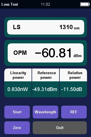
The Loss Tester module simultaneously activates the internal Laser Source (transmitter) and the Optical Power Meter (receiver) to measure the total insertion loss of a fiber optic link.
Testing Procedure:
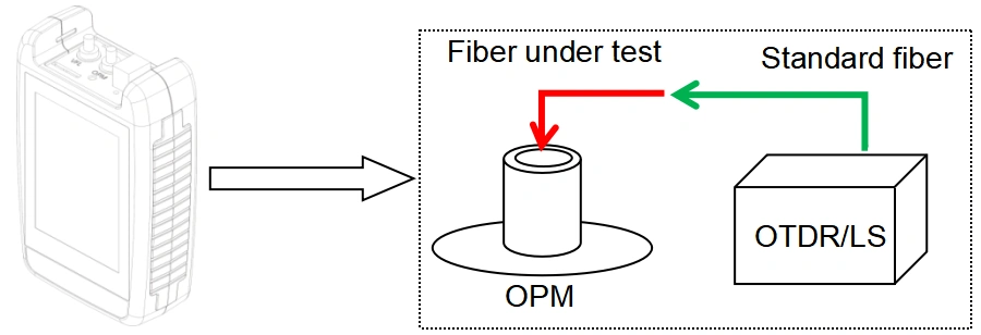
- Preparation: Connect the Laser Source port to the OPM port using a standard reference patch cord. Then, open the ‘Loss Test’ module from the main interface.
- Select Wavelength: Press the [Wavelength] button to select your desired testing wavelength.
- Set Reference: Allow the laser source to stabilize (a 5-minute warm-up is recommended). Press the [Reference] button. The Relative Power will reset to 0.00 dB, and the Reference Value will display the current absolute output power of the laser.
- Connect the Target Fiber: Carefully disconnect the reference cord from the OPM port (⚠️ Note: Do not disconnect the cord from the Laser Source port, as this will invalidate your reference). Use an adapter to connect the fiber under test (FUT) in series between the reference cord and the OPM port.
- Read the Result: The Relative Power value now displayed on the screen indicates the exact insertion loss of the tested fiber.