Description
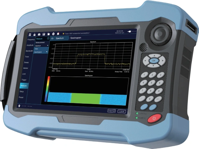
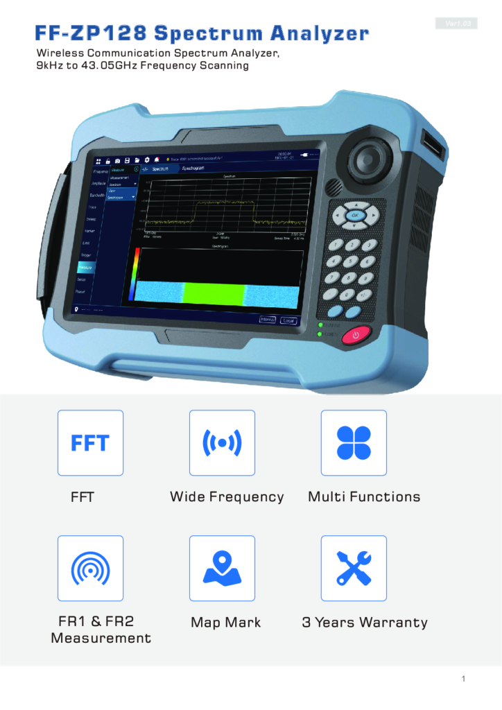
FF-ZP128 Spectrum Analyzer
Wireless Communication Spectrum Analyzer, 9kHz to 43.05GHz Frequency Scanning
Measurement Senarios
Wireless Communication
– Wireless Spectrum Management
– Base station measurement and monitoring
– Cable and antenna measurement
– Interference analysis and
– localization
Satellite Communication
– Satellite communication system debugging
– Troubleshooting of Satellite
– Communication System
– Performance optimization of
– satellite communication system
Radar Communication
– Radar signal measurement
– Diagnosis and troubleshooting of radar system faults
Military and Defense
– Electronic Warfare and Spectrum Monitoring
– Radio communication reconnaissance and military equipment spectrum management
– Interference source search and spectrum network cleaning
Others
– Drone Countermeasure
– Electromagnetic compatibility and electronic testing
– Research and Education
– Artificial intelligence, semiconductor, automotive, new energy, power electronics testing
– Physics and Medicine
– Radio, television, and audio testing
| Spectrum analysis | |
| Frequency range | 9kHz~43.05GHz |
| Real time bandwidth | 100MHz |
| Scanning speed | 10.74ms@ Span=0.31GHz RBW=VBW=100kHz65.4ms@ Span=4.24GHz RBW=VBW=5MHz450.04ms@ Span=27.0GHz RBW=VBW=3MHz58.6ms@ Span=2.8GHz RBW=VBW=300kHz645.5ms@ Span=40GHz RBW=VBW=5MHz |
| Intermediate frequency bandwidth | 10MHz/100MHz |
| 100%POI | ≥9.3us |
| RBW | 1Hz~10MHz |
| VBW | 1Hz~10MHz |
| Measuring range | DANL~+20dBm |
| Attenuation range | 0dB~60dB (step 5dB) |
| Preamplifier | +20dB |
| Maximum input level | +20dBm,±50 VDC (Measurable), +27dBm,±50 VDC (Not Damaged) |
| Amplitude accuracy | 9 kHz ~ 2 MHZ: ±2.0 dB(Typical ±1.5dB)2 MHz ~ 15 GHZ: ±1.0 dB(Typical ±0.5dB)15 GHz ~ 23 GHZ: ±1.1dB(Typical ±0.6dB)23 GHz ~ 43 GHZ: ±1.8dB(Typical ±0.8dB) |
| Preamplifier (off)DANL 23+/-5 oC | 9 kHz ~ 10 MHz: -138 dBm, -140 dBm (Typical)10 MHz ~ 4.0 GHz: -143dBm, -145 dBm (Typical)4.0 ~ 14 GHz: -141 dBm, -142 dBm (Typical)14 ~ 20 GHz: -140 dBm , -142dBm (Typical)20 ~ 32 GHz: -142 dBm, -143 dBm (Typical)32 ~ 43 Ghz: -142 dBm, -145 dBm (Typical) |
| Preamplifier (on)DANL 23+/-5 oC | 9 kHz ~ 10 MHz: -160 dBm, -162 dBm (Typical)10 MHz ~ 4.0 GHz: -160 dBm , -161 dBm (Typical)4.0 ~ 14 GHz: -159 dBm , -160dBm (Typical)14 ~ 20 GHz: -160 dBm , -162 dBm (Typical)20 ~ 32 GHz: -160 dBm, -162 dBm (Typical)32 ~ 43 GHz:-161 dBm, -162 dBm (Typical) |
| SSB Phase Noise | -107 dBc/Hz @ 1GHz offset 10 kHz (typical value)-111 dBc/Hz @ 1GHz offset 100 kHz (typical value)-122 dBc/Hz @ 1GHz offset 1 MHz (typical value) |
| SFDR | <-75 dBc |
| Dynamic Range | >102 dB @ 2 Ghz |
| Second harmonic distortion | ≥20MHz:<-45dBc≥3GHz:<-65dBc≥10GHz:<-75dBc(test conditions: 0dB attenuation, -30dBm input) |
| Trigger | Free trigger, video trigger, periodic trigger, external trigger,RF burst trigger |
| Measure Item | Channel power, occupied bandwidth, adjacent channel ratio, spectrum transmission template |
| interference analysis | |
| Interference source search | channel power, received signal strength indication, GPS antenna |
| Interference positioning | Map, directional antenna |
| Demodulate | |
| Demodulation mode | AM, FM |
| Demodulation analysis | Baseband time-domain waveform, transmission power, carrier frequency offset, modulation depth (amplitude modulation), demodulation frequency offset (frequency modulation), signal-to-noise ratio |
| 5G NR | |
| RF channel power | Total channel power, peak to average power ratio, total power spectral density, and limit line testing |
| RF occupies bandwidth | Bandwidth occupancy, peak to average power ratio, total power, x dB bandwidth reduction, and limit line testing |
| Equivalent Isotropic Radiated Power | Receiving antenna gain, receiving cable loss, distance, path loss, maximum holding quantity, channel bandwidth, equivalent omnidirectional radiation power, maximum equivalent omnidirectional radiation power, limit line test |
| Single beam | Physical cell identification, sector identification, cell grouping, frequency error, time offset, auxiliary synchronization reference signal received power (dBm), auxiliary synchronization reference signal reception Received quality (dB), auxiliary synchronization signal signal-to-noise ratio (dB), synchronization and demodulation status identification, average error vector amplitude, peak error vector amplitude, power (dBm) |
| Multi-beam | Physical cell identification, sector identification, cell grouping, frequency error, time offset, auxiliary synchronization reference signal received power (dBm), auxiliary synchronization referenceSignal reception quality (dB), auxiliary synchronization signal signal-to-noise ratio (dB), synchronization and demodulation status identification, power (dBm) |
| Physical cell identification scanning | Multi physical cell identification, beam index, auxiliary synchronization reference signal received power (dBm), auxiliary synchronization reference signal received quality (dB), auxiliary synchronization Signal signal-to-noise ratio (dB), auxiliary synchronization signal error vector amplitude for each beam |
| Frequency range | 100MHz~43.05GHz |
| Frequency error | ≤ 10 Hz |
| Bandwidth | 5,10,15,20,25,30,40,50M,60,70,80,90,100MHz |
| Channel power accuracy | ±1.0 dBm |
| EVM | ± 2.0% (typical value, physical broadcast channel) |
| LTE | |
| Constellation map | Reference signal received power, root mean square/peak error vector amplitude, data error vector amplitude (QPSK, 16QAM, 64QAM, 256QAM), frequency offset (Hz, ppm), time offset (nanosecond) ± 2.0% (typical value, physical broadcast channel) |
| Data channel | RB power diagram, constellation diagram, demodulation type, RB power, root mean square/peak error vector amplitude, IQ offset |
| Channel | P-SS, S-SS, PBCH, PCFICH, PHICH, PDCCH, RS power (dBm), error vector amplitude (%), demodulation type, frequency offset |
| Power and Time Frame Analysis | Frame average power (dBm), frequency offset (Hz), orthogonal frequency division multiplexing symbol power (dBm), IQ offset (dB), root mean square/peak of error vector amplitude, root mean square/peak of data error vector amplitude |
| RF Analysis | Channel power, occupied bandwidth |
| Frequency error | ≤ 10 Hz |
| Bandwidth | 1.4MHz, 3MHz, 5MHz, 10MHz, 15MHz, 20MHz |
| Channel power accuracy | ±1.0 dBm (typical) |
| EVM | ±2.0 % (typical) |
| Part Number | Description |
| FF-ZP128 | Spectrum analyzer plateform |
| 128-S01 | SA interference analysis |
| 128-S02 | RTSA interference analysis |
| 128-S03 | Outdoor map |
| 128-S04 | Analog demodulation analysis |
| 128-S05 | Simulate demodulation audio playback |
| 128-S06 | Zero sweep wide intermediate frequency output |
| 128-S07 | Time gate function |
| 128-S08 | orientation analysis |
| 128-S09 | Real time spectrum analysis with a bandwidth of 50MHz |
| 128-S10 | Real time spectrum analysis with 100MHz bandwidth |
| 128-S11 | LTE analysis |
| 128-S12 | 5GNR measurement |
| 128-S13 | vector signal analysis |
| 128-S14 | phase noise measurement |
| 128-H01 | GPS/Beidou function |
| 128-H02 | WiFi wireless communication |
| 128-H03 | Transportation engineering box |
| 128-H04 | Off site measurement software package |
| 128-H05 | The power adapter |
| 128-H06 | 10Ah rechargeable lithium-ion battery |
| 128-H07 | 9K-30MHz directional antenna |
| 128-H08 | 20M-200MHz directional antenna |
| 128-H09 | 200M-500MHz directional antenna |
| 128-H10 | 500M-8GHz directional antenna |
| 128-H11 | 6G-20GHz directional antenna |
| 128-H12 | 18G-40GHz directional antenna |
| 128-H13 | 9K-8GHz handheld amplifier+USB electronic compass |
| 128-H14 | Antenna transport box |
| 128-H15 | 120MHz real-time analysis bandwidth |
| 128-H16 | 300MHz-8GHz omnidirectional antenna |
| 128-H17 | 20MHz-3GHz omnidirectional antenna |
| 128-H18 | 3GHz-40GHz omnidirectional antenna |
| 128-H19 | 300MHz-18GHz Omnidirectional Antenna |
Download
FAQ
Q: What is the frequency range of the FF-ZP128 Spectrum Analyzer?
A: The FF-ZP128 covers a broad frequency scanning range from 9 kHz to 43.05 GHz.
Q: What are the main measurement scenarios and applications for this analyzer? A: It is designed for wireless spectrum management and base station monitoring, satellite communication debugging, radar signal measurement, electronic warfare/military spectrum monitoring, drone countermeasures, and EMC/electronic testing.
Q: What is the real-time bandwidth and Probability of Intercept (POI)?
A: The device features a real-time bandwidth of 100 MHz and a 100% POI of $\ge 9.3\ \mu\text{s}$.
Q: Does the FF-ZP128 support 5G NR and LTE signal analysis?
A: Yes, optional software modules support both 5G NR (RF channel power, multi-beam, cell ID scanning, EIRP) and LTE analysis (constellation maps, data/channel power, EVM, time frame analysis).
Q: What demodulation and interference location capabilities does it offer?
A: It supports AM and FM demodulation modes (including baseband time-domain waveform analysis and audio playback). For interference analysis, it provides channel power measurement, RSSI, GPS integration, directional antenna pairing, and mapping tools.
Q: What optional antennas and accessories are available for the FF-ZP128?
A: Available option packages include directional antennas (ranging from 9 kHz up to 40 GHz), omnidirectional antennas, hand-held amplifiers, GPS/Beidou modules, WiFi connectivity, a 10 Ah rechargeable lithium-ion battery, and transportation boxes.