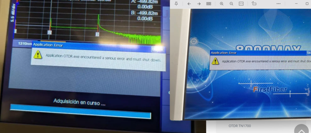
IMPORTANT NOTICE: This technical manual is specifically designed to resolve system-level boot failures encountered during the startup process of the 8000MAX OTDR (as shown in Right Picture). If the issue you are experiencing occurs during actual OTDR testing or operation (as shown in Left Picture), this manual is not applicable. For testing-related issues, please refer to our dedicated troubleshooting blog
https://firstfiber.cn/blog-detail/the-method-to-solve-8000max-otdr-bug-application-otdrexe-encountered-a-serious-error-and-must-shut-down
or contact our technical support team directly at tech@FirstFiber.cn.
Phase 1: Hardware System Flashing Procedure
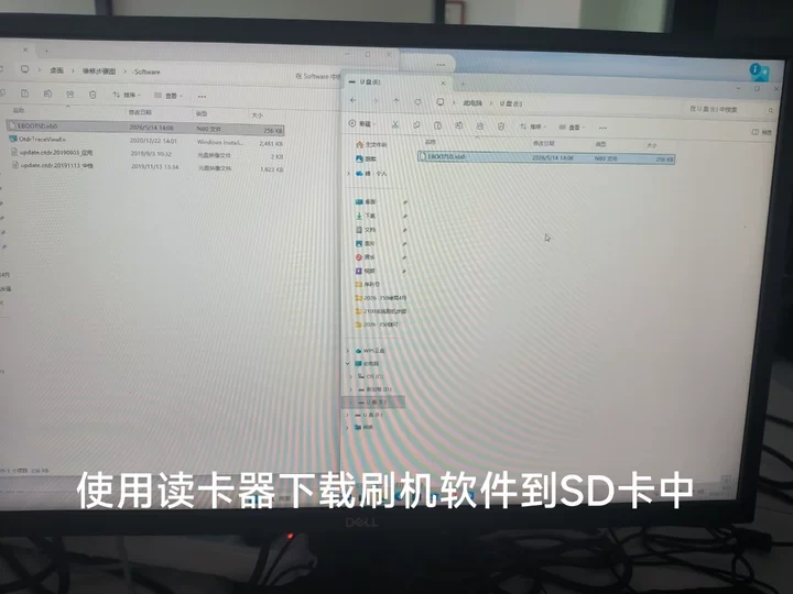
| Pre-requisites & Preparation Firmware Preparation: Use an external card reader to copy the system flashing binary file EBOOTSD.nb0 into the root directory of an SD card. |
Step-by-Step Hardware Disassembly & Flashing
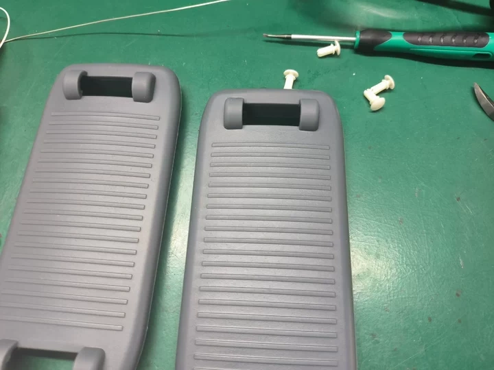
| Step 1: Remove the Securing Bracket Carefully detach and remove the securing clamps/brackets along with their associated hardware accessories. |
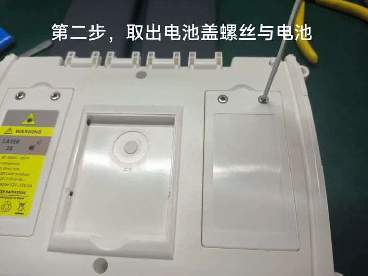
Step 2: Remove the Battery Compartment
Unscrew the battery compartment cover, remove the protective plate, and safely extract the battery
pack.
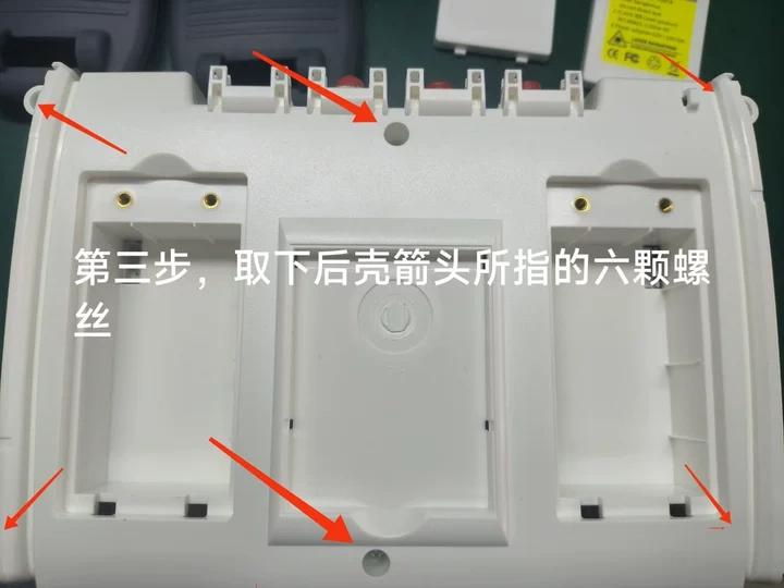
Step 3: Detach the Rear Housing
Locate and remove the six screws indicated by the arrows on the back cover. Gently separate and lift off
the rear casing/housing of the device.
Step 4: Insert the Flashing SD Card
Insert the prepared SD card loaded with the EBOOTSD.nb0 system flashing file into the device’s SD
card slot.
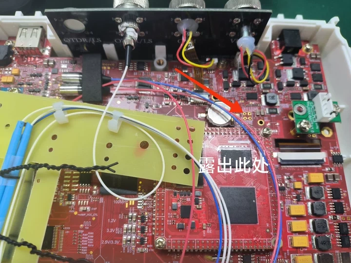
Step 5: Expose the Programming Port
Unscrew and remove the two securing screws indicated by the arrows to expose the internal system
flashing/programming port interface on the circuit board.
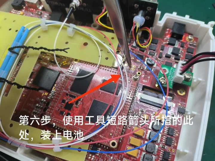
Step 6: Short-Circuit the Programming Pins
Use an appropriate conductive tool (such as precision tweezers) to short-circuit the designated
programming pinholes indicated by the arrow, then temporarily re-insert the battery pack to supply
power.
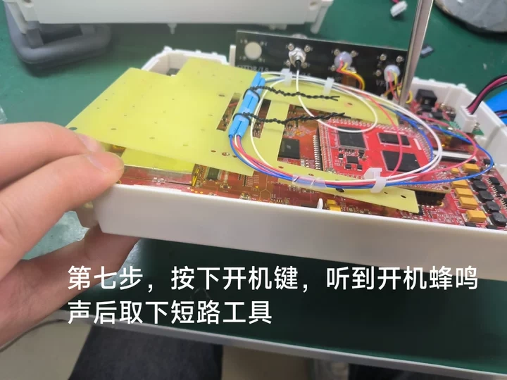
Step 7: Initiate the Flashing Process
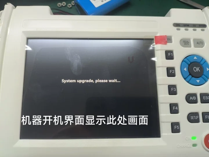
Press and hold the Power button. The moment you hear the device emit its startup beep sound,
immediately remove the short-circuit tool. The screen will display the system initialization prompt: “System upgrade, please wait…”.
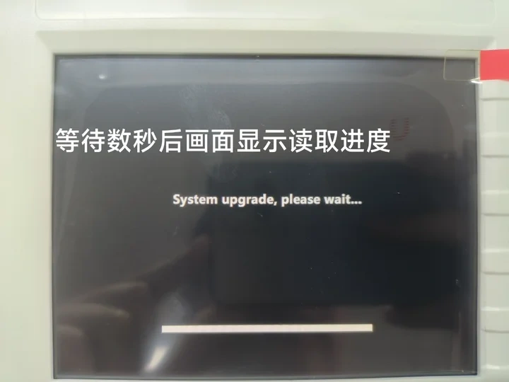
Step 8: Data Transmission Progress
After a few seconds, a progress loading bar will appear on the screen, showing that the system
firmware data is successfully being read from the SD card.
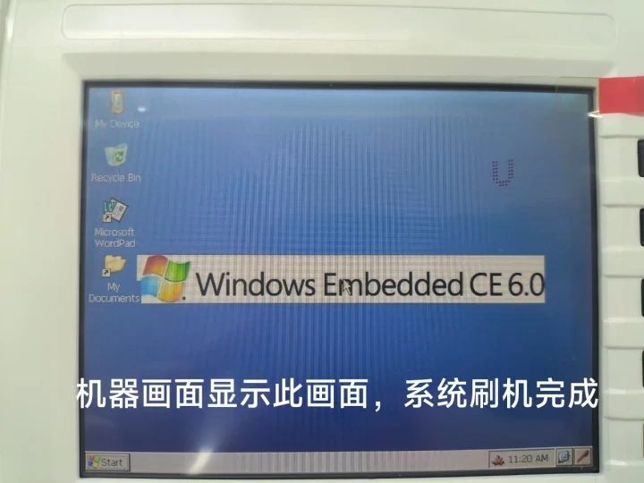
Step 9: Flashing Completion Status
Once the progress bar reaches 100%, the device will automatically boot into the Windows Embedded
CE 6.0 desktop layout, confirming a successful flashing operation.
Post-Flashing Note: Once system verification is successful, reassemble all the hardware modules by
reversing the disassembly steps in sequence.
Phase 2: On-Device System Software Upgrade
| Follow the steps below to initialize and perform the core software environment setup within Windows CE |
Step-by-Step System Software Upgrade
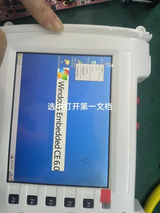
| Step 1: Access Device File Storage On the Windows CE home screen desktop, double-click to open the root storage folder directory labeled “My Device”. |
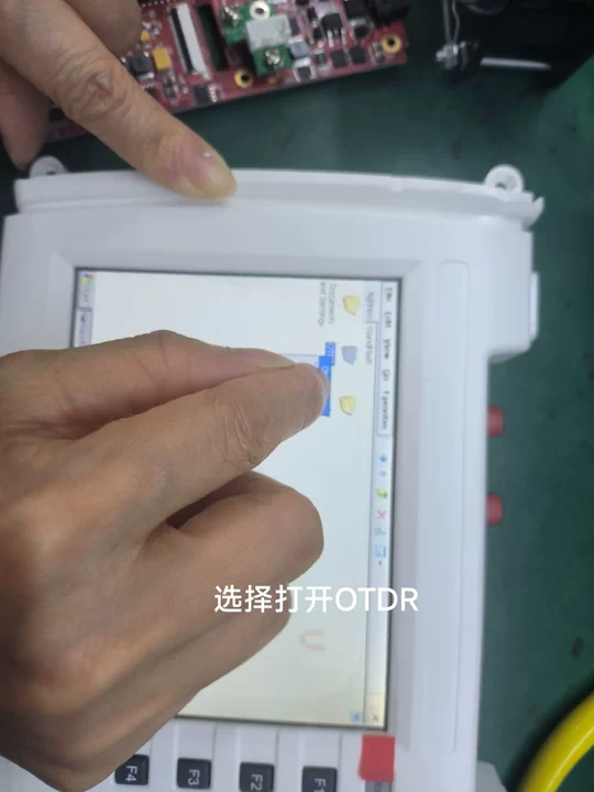
Step 2: Open the Target OTDR Directory
Locate and open the dedicated application storage directory named “OTDR”.
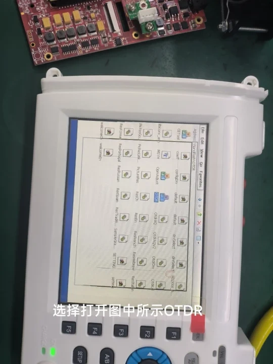
Step 3: Execute the OTDR Software Core
Double-click on the main executable binary icon within the directory to launch the OTDR software application.
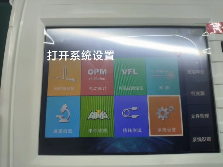
Step 4: Enter System Settings Menu
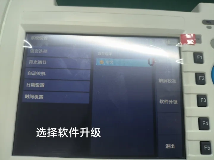
From the main software interface layout, navigate to and open the “System Settings” panel.
Step 5: Execute Firmware & Software Upgrade
Tap the “Upgrade” button configuration to deploy and finalize the system updates.